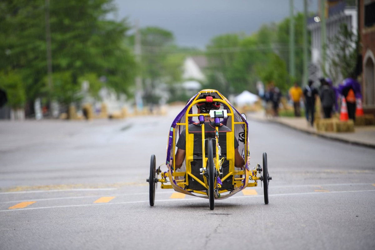
The frame is the foundation for every human powered vehicle. As such, it must be both safe and comfortable while providing the support needed for the other subsystems in the vehicle and the rider. It is our goal to learn from the mistakes and misdirection of past "Ke Koa" teams in order to improve upon their frame concepts and develop a better one for ourselves.
The Frame
The Design Process


Figure 1: Initial design concepts for the HPV frame
Several factors were taken into account when deciding upon the final frame. Some of them include, but are not limited to:
-
Manufacturability — Due to an early competition date, the ability to manufacture the vehicle both efficiently and quickly was weighed heavily when making the decision for our frame.
-
Even force distribution — It goes without saying that the frame would need to have the weight of the rider evenly distributed throughout to avoid breaking in prone areas.
-
Strength of the material used — A strong material would also help with the frame's ability to withstand higher forces.
-
Weight of the material used — While we were not necessarily looking for the heaviest material to use, we also wanted a material that would lower our center of gravity and reduce the risk of rollover.
-
Weldability — One of the mistakes that prior "Ke Koa" teams made was choosing a material that was difficult to weld; this resulted in breaking during competition that negatively impacted their chances of winning.

Figure 2: The broken weld from the 2016-2017 HPV "Ke Koa" team
The Frame
Taking into account the criteria we came up with for our frame, the team was able to decide on its final design: a thin, square, tadpole style recumbent tricycle. The material that was selected to make the frame was 4130 Alloy (Chromoly) Steel. While weighing the heaviest out of all the options considered, a combination of its overall cost, strength, and weldability made it the obvious choice for this year's frame. Round tubing, as opposed to square tubing, was chosen for the roll cage design due to its aerodynamics and high torsional strength. For the base of the frame, square tubing was chosen for its higher bending strength and larger area for welding which cacn be utilized when attaching the frame to the hinge innovation. Figure 3 shows a SolidWorks model of the final concept design for our frame.
Prior to choosing a final design for the frame, several different designs were sketched and considered. Among these designs, a single bar frame, square frame, and curved frame were the ones that were discussed. Hand drawn schematics of each type were created by the members of the frame subsystem and brought up with the rest of the team. Figure 1 shows some of the different schematics that were considered when designing the final frame.

Figure 3: Final design concept of our frame design
The Hinge
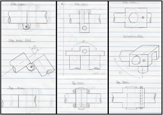
Other than the frame itself, an important component that was a part of the frame subsystem was the hinge. Without the hinge, the main innovation to our human powered vehicle would not be feasible. As with the frame, several different concept sketches were made for the hinge. Figure 4 shows the the three main concepts for the hinge.

Figure 4: Three concept sketches for the hinge
Figure 5: Final design for the hinge
Again, such as with the frame itself, certain considerations had to weighed when choosing the design for the hinge. The criteria that was used to judge the hinge point are as follows:
-
Range of motion — A hinge that would allow for the tricycle to fold in an array of angle was needed.
-
Simplicity — As with manufacturing the frame itself, manufacturing the hinge would have to be as simple as possible to accommodate for our shorter manufacturing period.
-
Feasibility — Weighed the most out of all the criteria used to judge our hinge, it would need to be something we could actually manufacture with the skill set and materials we posses.
With these criteria in mind, the obvious choice for our hinge became the second concept sketch shown. One difference between the drawn figure and the SolidWorks model was the added bolt above the hinge. After consideration of the design, it was figured that the hinge alone would not be able to support the forces placed upon it, so the bolt was added for additional structural integrity. Figure 5 models what that hinge will look like.
The Seat
Another main component of the frame subsystem is the seating for the rider. An integral part of the frame, the seat gives the rider comfort. The seat we planned to incorporate would also provide adjustability, giving our vehicle the ability to accommodate riders of many different heights.
Certain considerations were taken into account when designing the seat for the vehicle. As it was the component of the frame that would allow for rider adjustability, the design became a top priority to ensure that this feature would work. Some of the considerations looked into are as follows:
-
Range of motion — As the seating would need to be adjustable to allow for different rider heights and leg lengths, the seating mount would need to have an appropriate range of motion to allow for this adjustment
-
Simplicity — Manufacturing the mount must be simple enough to justify keeping it, rather than discarding the adjustable idea altogether
-
Strength of the material used — While not needing to be as strong as the main frame itself, the material used in the seating must be strong enough to hold the rider's weight both statically and in motion
-
Ergonomics — The seating must be comfortable enough for the rider to stay in it for long periods of time

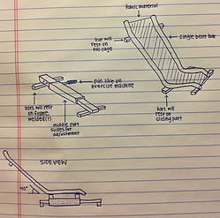
Figure 6: One design concept for the seating
As of right now, it has been decided that the seat will be purchased from a vendor to cut back on the materials needed to manufacture while also ensuring that time is saved during the manufacturing process. The seat going to be purchased is a "trike" style seat made by the THOR Composite Recumbent Seat company. With the design of the seat, riders will be able to stay in place while taking harsh turns on the track, giving our vehicle an extra ounce of safety and ergonomics.

With the seat chosen, the only worry with how to implement it into the design of the vehicle was the seat mount. The trike style seat from THOR already comes with holes drilled into the back and bottom of the seat to allow for easy manufacturing. The only part we would need is a place to actually mount the seat. After careful deliberation, one was chosen that would use a sliding mechanic to allow the seat to adjust to the rider's preference. With the ability to allow the rider to adjust the seat either three inches forward or three inches backward from the neutral position, the mechanism would use dual pins to keep the mount in place when not being adjusted. This idea utilizes the square tubing that was decided upon earlier, allowing a smaller square tube to slide through a larger one. This design can be found in Figure 7.

Figure 7: THOR Trike seat
The Safety Harness
As required by the ASME HPVC, a safety harness was implemented into the plans for the frame subsystem. It was decided that, instead of manufacturing our own safety harness, one would be bought from the Tanaka company. Known for their reliability, a 4-point harness was chosen for our purposes. It is proposed that it will be attached to the vehicle via the roll cage, but suggestions and ideas for the positioning are still being made.
What's Next?
While all main components of the frame have been finalized, there are still some concerns for the subsystem. One of the main concerns is how the hinge of the vehicle will be manufactured. Currently, the team is looking into using machinery such as lathes to build the hinge ourselves since we can not seem to find ready-made ones online that fit all our criteria and standards. Another main concern is the structural integrity of our roll cage. The team is looking into adding crossbeams to its design in order to give it more strength. The crossbeams also have an extra bonus of allowing us to skip designing a back mount for the seat altogether, as the seat could rest against the crossbeam instead. Finally, one of the last concerns is the lead time for materials to arrive to us. To combat this, the team has already started purchasing materials in hopes they will arrive just as winter break begins. These concerns must see some sort of resolve before or while we move into the manufacturing phase.
